Sketching in 3D can be challenging, but it is a very powerful tool once you
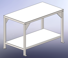
understand the basics. It is especially useful when creating weldment parts
like this workbench. This example will demonstrate how to create a 3D sketch
that will govern the overall size of this welded frame workbench.
Unlike sketching in 2D, where you are required to select a plane, face, or
edge to begin a sketch, it is not necessary to select one of these references
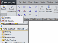
to begin a 3D Sketch. Simply selecting the 3D Sketch command, located in the
drop down menu below the Sketch Icon on the Sketch tab of the Command Manager,
places you in the 3D Sketch environment.
The important thing to be aware of when sketching in 3D is the orientation of
the cursor as you begin to place sketch entities in the sketch environment.
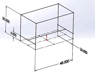
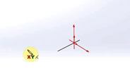
The first entity I have chosen to begin the sketch of my frame is a center
rectangle which I plan to place centered at the origin and resting on the top
plane. The cursor indicates to me the orientation that the sketch entity will
assume when placed in the 3D environment. In the image at left, the system
feedback indicates that if I begin sketching, the entity will be placed on a
plane parallel to the Front plane. Notice the red highlighted axes at the
origin as well as the
XY beneath my cursor. In order to change this I need to press the TAB key on my
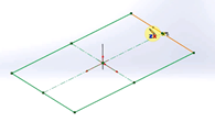
keyboard to cycle through the available plane orientations. After cycling to
the desired orientation,
ZX, with the TAB key, I now place my center rectangle at the origin, make it
construction geometry, and dimension it 26” X 48”.
Now I am ready to begin adding the actual geometry that will represent the
frame in the weldment. As soon as I activate the line tool, my cursor reflects
the last plane orientation I sketched on,
ZX, and since I am going to sketch one of the ends of my frame, I need to change
the orientation to
XY and select one of the vertices of the construction rectangle. Beginning at
the vertex on the corner, I sketch 3 lines up, over, and down, terminating at
the opposite vertex of my rectangle. I can use the system feedback inference
lines to capture sketch relation automatically. These are based on the
orientation that I am sketching on. I can also add relations after I sketch,
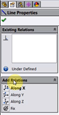
which is a practice that I employ often. In addition to the relations
typically found in SOLIDWORKS such as
equal, perpendicular, concentric, etc., sketching in 3D provides a
few extra types of relations that are not found in the 2D environment. These
are relations that basically align sketch entities parallel along the primary
system axes X, Y, and Z.
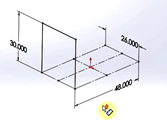
I will add these to the lines I just sketched along with a dimension to
establish the height of my frame at 30”. I now have the overall width, length,
and height of my frame established. For the other end on my frame, I will
repeat the process with three more lines placed on the opposite end of the
construction rectangle and using the same
XY orientation of my cursor. This time I will select one of the vertical lines
and make it equal to one of the previous vertical lines one the other end in
order for the height of both ends to be controlled by one dimension.
At this point I don’t need to be concerned with the TAB key and the
orientation of my cursor. When I add the two lines that will connect the ends
of the frame, selecting the vertices will add coincident relations of the end
points of the new lines to the existing geometry. The orientation does not
matter.

Adding geometry for a shelf in my table is handled the same way. As long as I
select existing geometry, defining endpoints with coincident relations, I
don’t need to be concerned with the orientation of the cursor. In my example
here, I inserted lines at both ends coincident to the uprights, added
Along X relationships to them, and dimensioned one
end with a 6” dimension. Adding the line down the center coincident to the
midpoints of these lines with an Along Z relation,
ties the shelf entities together. Now my 3D sketch frame is ready to accept
the structural members of my weldment. This 3D sketch, containing only the
four critical dimensions, now governs the overall size of my frame and shelf
position, and as is the magic of SOLIDWORKS parametric modeling, no matter
what size I change these dimensions to, all components of my frame will update
as well as all associated documents.