SOLIDWORKS Composer is all about telling a story, whether the story is how an
assembly gets from a pile of parts on the floor to comfortable furniture, or
how to identify the correct replacement part for your engine. This is an
entirely different job from the detailed technical drawing work done in
SOLIDWORKS Drawings, but many of the tools carry over. Exploded line sketches,
labels and balloons, dimensions and section views are all tools that look
familiar from the SOLIDWORKS environment but give us a variety of new
capabilities in
Composer.
Path Tool
Paths are used to create 3D lines (2D lines in 3D space) that illustrate a
path from components neutral locations. Paths are divided up into two
environments and two different types. These tools become available once you’ve
selected a geometry actor that has been translated from its neutral position.
The environments are simply there so that you can create both types of basic
paths in both the View and Animation environment.
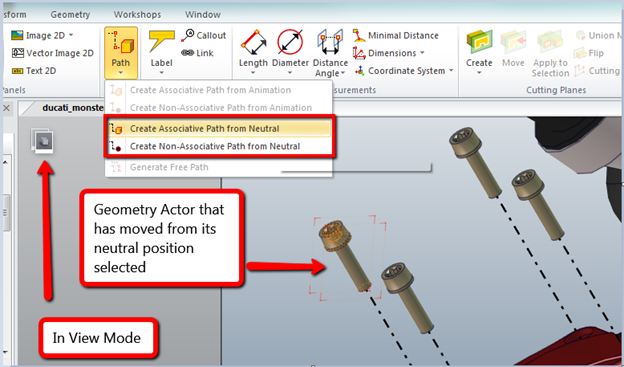
There is a significant difference between Associative Paths and
Non-Associative Paths. Associative paths will update the path line if the
Actor ever changes position. Non-Associative path lines are just snapshots of
the current position. I use Associative Paths almost exclusively because you
can use the same path line for multiple positions of the part or fine tune the
location without needing to think about updating the path line.
The last option in the Paths toolbar is the Generate Free Path tool. This
becomes available when you have an existing path line selected. By clicking on
Generate Free Path Composer will create a copy of the existing path that has
on association and hide the path that was used to create it. The original path
still exists, check your annotations to find it. From that point you can drag
the free path wherever you want. This is a great tool if the path lines are
close but not quite where you want them.
Label Tool
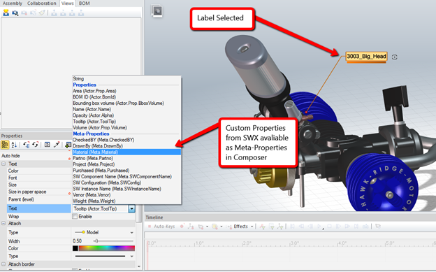
This tool is about as straight forward as it can get: select the tool, click
where you want the tooltip attached to. The information displayed is all up to
you. If the “Meta-Properties” are available, meaning that the parts in
Composer came from a
SOLIDWORKS model with custom properties and you chose to import them, you can display
the properties in the label.
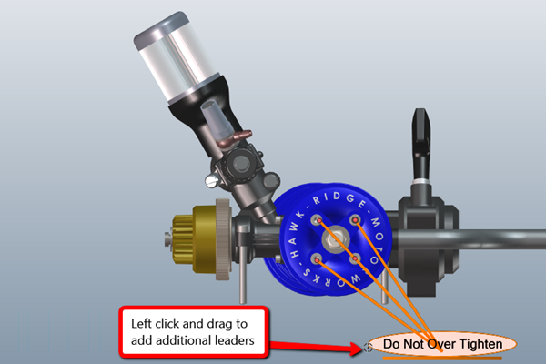
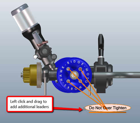
There are a host of other options in the label tool drop down. Label with
Multiple Actors is may seem a bit confusing to use at first because at first
glance it looks like you’ve just created a normal Label. The trick is to look
for the crosshair symbol next to the Label text box in the graphics area. Left
click on the icon and drag it to the new leader location. You don’t
necessarily need to use the Label with Multiple Actors tool to get the
crosshair. It should display next to a regular Label as well.
The rest of the label tools are pretty specific including ones used to callout
surface areas, volumes, or even point coordinates. There’s also a mysterious
one called pipe length. This is specific to CATIA V4 files so unless you’re
using those don’t worry about it, Composer is just showing off its roots.
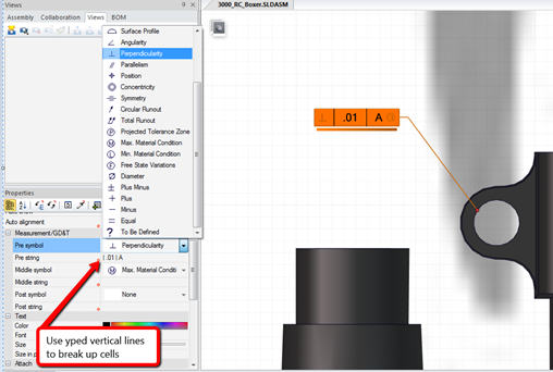
The last one in the list is GD&T, and again it’s about what you’d expect
from a labeling tool. I do like that this tool is eager to snap onto specific
edges of your model. There are drop-down menus in the Label properties to
select your tolerance type and text strings to fill out the rest. One quick
tip though, to get the text broken up into boxes use the vertical line – | –
on your keyboard.


I surfed through internet but failed to find how additional leaders of the labels or callouts can be deleted once created.
In order to to remove additional leaders you have to first select the label or callout. Once selected you will see a little bullseye icon immediately to the right or leftl, depending on what side the leader attachment is on, click and drag the attachment point of the unwanted leader to this bullseye icon and it will be removed.