Injection molding is a complicated process and it can be difficult to predict
when defects will occur. Troubleshooting is often required to address issues
discovered after an initial trial run. Unfortunately, the mold has already
been manufactured by this point so adjustments are limited and costly.
It is much less problematic if issues can be sorted out during the design
stage. Fortunately, many defects can be avoided by following plastic part
design best practices and mold flow simulation software such as SOLIDWORKS
Plastics can provide additional insight. The table below includes a list of
common injection molding defects, how to detect them in SOLIDWORKS Plastics,
and suggested solutions.
Defect |
Description |
How to Detect in SOLIDWORKS Plastics |
Suggested Solution |
|---|---|---|---|
| Burn Marks |
Burn marks appear when the air is trapped in the cavity and compressed to combustion. |
Select the Air Traps checkbox in the Flow Results. Burn marks might occur at these locations if combustion occurs. A Venting Pressure plot (SOLIDWORKS Plastics Professional) can provide a more detailed look at the problem. |
Add air vents to release the pressure. Decreasing the fill rate can give the air more time to escape. |
| Flash |
Flash occurs when insufficient clamping force or mold imperfections allow some molten plastic to escape the mold cavity. |
The Flow Results Summary indicates the required clamping force to successfully mold the part. If this value is greater than the clamping force of your machine, flash can occur. |
Flash is simple to avoid if your machine can provide sufficient clamping force. However, the required clamping force can be reduced by reducing the injection speed and pressure. |
| Jetting |
Excessive injection speed can cause the material to jet through the gate instead of maintaining a cohesive flow front. The turbulence results in a snake-like pattern on the surface of the part. |
Ensure that the Volume of Fluid Algorithm is set to Direct (Fill Settings -> Advanced -> Options). If jetting occurs, it will be shown during an animation of the Fill Time plot. Isosurface Mode can be helpful to see inside the part volume. |
Increase the gate size or adjust the melt temperature to allow a proper flow front to develop. If a small gate is necessary, locate the gate near an appropriate obstruction such as a rib or boss. |
| Polymer Degradation |
High shear heating can degrade the material, lead to discoloration, and significantly affect the physical properties of the part. |
The Temperature Growth at End of Fill plot indicates the amount of heating due to shear. The Shear Stress and Shear Rate plots can provide additional insight. |
Shear heating effects can be minimized by increasing part, runner, and gate thicknesses, replacing sharp corners with rounded corners, increasing mold and melt temperatures, and decreasing the flow rate. |
| Short Shot |
A short shot occurs when the flow front freezes before the cavity has filled and results in an incomplete part. Flow restrictions, long or complex flow paths, inadequate venting, low melt or mold temperatures, and low injection speed or pressure are some common causes. |
The Results Adviser indicates if the maximum injection pressure is exceeded and a short shot is detected. |
Depending on the cause of the short shot, a complete fill may be achieved by increasing part, runner, and gate thicknesses, changing the gate locations, increasing the number of gate locations, increasing mold and melt temperatures, or using a higher flowing material. |
| Sink Marks |
Sink marks are depressions that develop on the surface of the part as a result of significant shrinkage. This is common at thicker part sections, which require more time to cool. |
The Sink Marks plot (SOLIDWORKS Plastics Standard) identifies sink mark locations and estimates the amount of depression. A Warp analysis (SOLIDWORKS Plastics Premium) can provide a more accurate Sink Mark Profile plot. |
Design parts with uniform wall thickness and use ribs and bosses that are approximately 30% thinner. Place injection locations at thicker sections to increase packing pressure in those areas. |
| Voids |
Voids form within the part when there is insufficient packing pressure. Similar to sink marks, they typically occur at thicker areas, but the shrinkage creates an internal pocket instead of a surface depression. |
The Pressure at End of Fill (SOLIDWORKS Plastics Standard) and Pressure at End of Packing (SOLIDWORKS Plastics Professional) plots can highlight areas of low pressure. |
Design parts with uniform wall thickness and use ribs and bosses that are approximately 30% thinner. Place injection locations at thicker sections to increase packing pressure in those areas. |
| Warping |
Part warpage occurs as a result of non-uniform shrinkage and molded-in stress distributions. Common causes include uneven cooling and variable packing. |
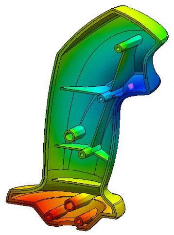
The Volumetric Shrinkage at End of Fill (SOLIDWORKS Plastics Standard) and Volumetric Shrinkage at End of Packing (SOLIDWORKS Plastics Professional) plots can indicate areas expected to undergo high rates of shrinkage and cause warpage. A full Warp analysis (SOLIDWORKS Plastics Premium) can determine the deformed part shape. |
Choose injection locations that result in the uniform filling, pressure, and temperature distributions. Aim to minimize volumetric shrinkage, but more importantly, try to achieve uniform volumetric shrinkage. |
| Weld Lines |
Weld lines develop where flow fronts merge together. They often result in cosmetic defects and the strength of the part in the area is reduced. |
Select the Weld Lines checkbox in the Flow Results. |
The position of the weld lines can be changed by moving the injection locations or through a design change. Increased material temperature can improve bonding between the flow fronts. |
Don’t forget to come see us at the
Pacific Design & Manufacturing Expo
(Booth 3994) in Anaheim February 7-9, 2017. For more information, check out
our
YouTube channel
or contact us at
Hawk Ridge Systems
today. Thanks for reading!