SOLIDWORKS Routing
is a powerful add-in included with
SOLIDWORKS Premium. Routing has a wealth of useful tools to improve your efficiency when
designing routes that contain electrical components, tubes ( flexible hoses,
straight sections with elbows, or form bends), and pipes (straight sections
with elbows or form bends). I love how the software starts a route for me
the moment that I drop a fitting or connector into an assembly.
While this automation can help to increase design efficiency, you still need
to pay attention to your workflow to make sure that the route is oriented
correctly. You may have been frustrated by this in the past if you have ever
needed to orient a flange on the end of a pipe to match a particular
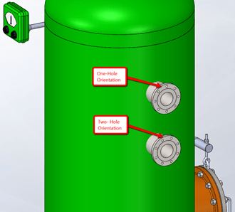
orientation. Typically, the two-hole flange orientation (two holes are
horizontal at the top) is most common, but there are times that the one-hole
orientation (only one hole at the top) may be required.
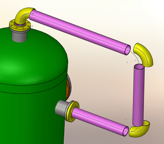
Knowing and using this design intent requires some planning to be effective.
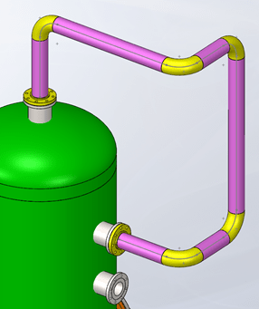
When I don’t plan properly and I try to change the orientation of the flange
AFTER I have created several route components and parts, I get results like
those shown in the following image.
At first, I was really happy with Routing in
SOLIDWORKS 2014, it appeared to fix the issue. But, as I continued testing, I still ran
into issues. Eventually, I found the secret to getting consistent predictable
behavior.
Since the tanks, vessels, pumps, or other components with flanges that are
already welded to them are usually placed in the assembly before the pipe
route is created, I am in luck. I know the orientation that I need for my
flange. Below is the necessary workflow:
1. Start your pipe route as usual by dropping a flange into your assembly and
locating it to a component.
2. After you define the route properties, through the property manager, you
may optionally add the end flange if it must be oriented as well. The next
step is most important!
3. This is CRITICAL, immediately exit the route so you are at the Edit
Assembly level before any other components or fillets are added to your
sketch.
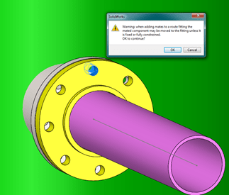
4. Add a concentric mate to align the holes on the flange of the route to
the holes on the component you wish to connect to. Hit OK if you get a
warning message like the one above.
5. Edit the route again and continue as you normally would with some of the
great Routing tools such as Auto Route or dragging components from your design
library.
Happy routing! And remember, if flange position is key, be sure to orient the
end flanges BEFORE you add any more components or create any more route
segments.
For more tips like this, be sure to
subscribe to our blog
or
our YouTube channel!