If one just looks at the name “sweep feature”, it’s not readily apparent what
this actually is. In my mind I hear “Sweep the leg!” from the first Karate Kid, which can’t possibly be correct. In all
seriousness, when it comes to
SOLIDWORKS, the sweep is a powerful tool to create useful geometry when a regular boss
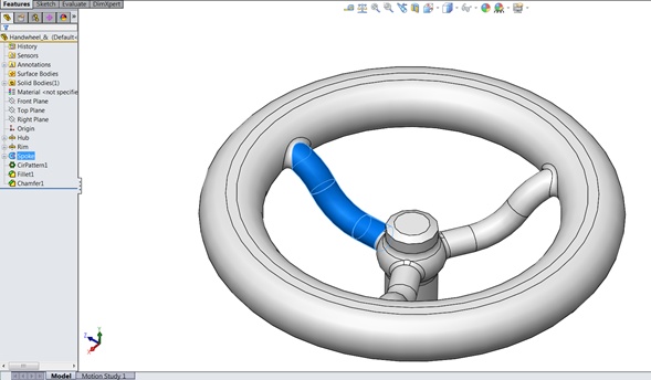
won’t work. Using a sweep isn’t as confusing as it seems. The spoke of this
wheel is an example of a swept boss/base:
I will be referring to the swept boss/base feature for this article, but the
principles apply to a swept cut as well. The basics of a sweep are:
-
Uses a minimum of 2 separate entities: a profile and a path; also, guide
curves can be used to control the shape - The path must intersect the plane of the profile
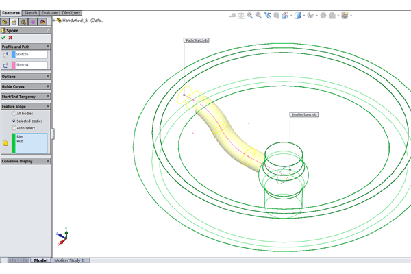
The “profile” is the shape that you want the outside of the sweep to have, and
the “path” is what you want the profile to travel along/follow. In the spoke
example, the profile and path sketches are identified and highlighted as blue
and pink respectively:
Seems simple enough right? However…
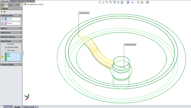
In my experience, the first condition is pretty intuitive, but the second
condition causes the most confusion. Here is an example of two sketches that
won’t create a sweep because the path isn’t intersecting the profile plane:

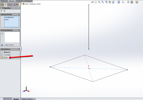
The simplest way to make sure both sketches intersect is to use the Pierce
Relation. This relation makes a point pierce an axis, edge, or curve in
another sketch, which is what we are looking for between the profile and the
path of a sweep.
In this case, I’ve selected the endpoint of the vertical line and one of the
construction lines from the center rectangle sketch:
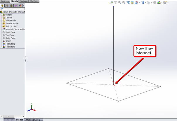
Add the Pierce Relation and the endpoint and construction line touch:
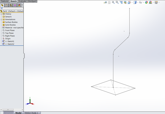
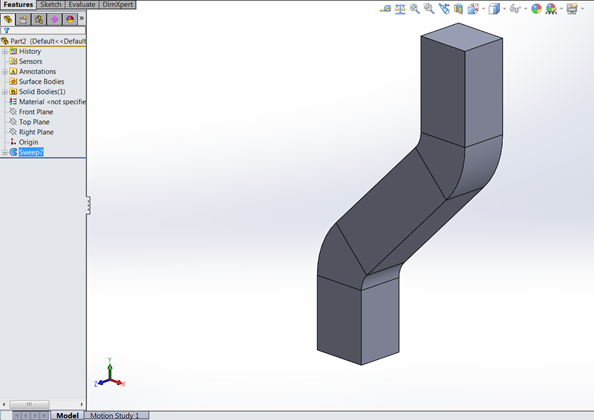
By adding some more lines and a couple of fillets to Sketch2, my path sketch,
we can make a shape that we couldn’t do with an extruded boss/base and we’re
ready to create the Swept Boss/Base:
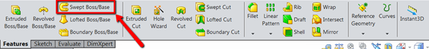
Go to the Features tab of the Command Manager and click on the Swept Boss/Base
to go into the feature.
If you have your two sketches selected already, SolidWorks should be able to
auto-populate the Profile and Path field. If these aren’t selected, you can
click on these in the graphics area or from the Flyout Feature Manager Tree.
The blue box is for the Profile and the pink box is for the Path:
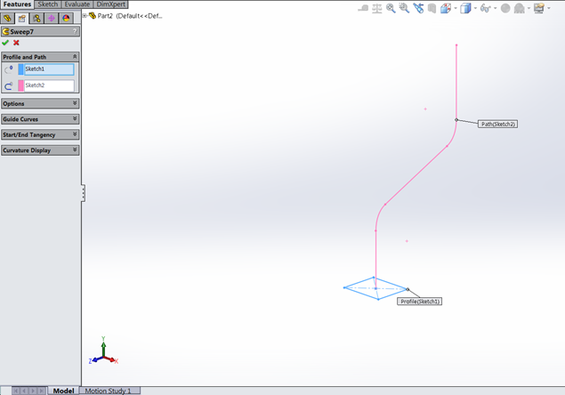
Just hit the green check and you have a sweep!
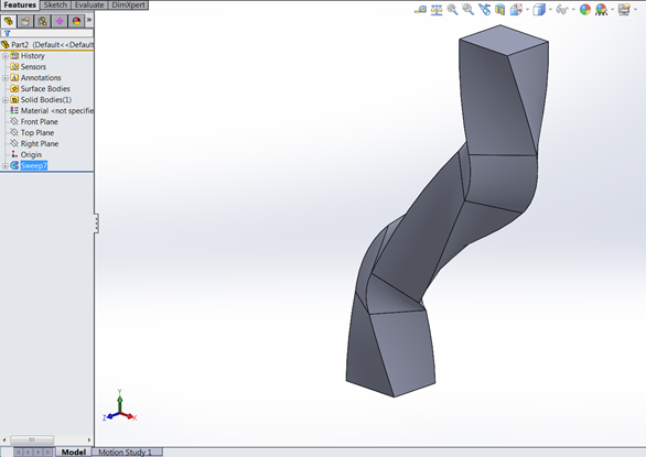
If a twist is needed in the part, you don’t have to change the path to a helix
(that might be a future blog article…) Within the sweep feature, under the
Options area, the Orientation/twist type can be modified from Follow Path (the
default) to Twist Along Path by hitting the drop down:

Select if the twist is defined by Degrees, Radians or Turns, put in the value
of the twist and hit the green check:
For a video of the basic sweep feature, along with an introduction to
Selection Sets, please take a look at
our YouTube video
below.
Good luck sweeping and thanks for reading!