In this series, I will design a racing road bicycle with the help of
SOLIDWORKS. Starting with the geometry, I will move on to the tube shapes
and componentry to come up with an engineered speed machine.What’s to
come?
Part 1: Frame Geometry Optimization – Using 3D Sketches,
Weldments, and Static Analysis to optimize the frame geometry
Part 2: Tube Shape Optimization 1 – Using Surfacing and
Static Analysis to define the shape of the tubes
Part 3: Tube Shape Optimization 2 – Using
CFD analysis
to optimize the aerodynamic efficiency of the tube shapes
Part 4: Components and Details – Finishing up the rest of the
bike. Because why not?
Part 1: Frame Geometry
The intent of this project is to use parametric mechanical design software (SOLIDWORKS) to engineer a racing road bike.
The key optimization parameters will be:
- Power Transfer
- Handling
- Aerodynamics
Comfort will be considered, but I’m not looking to design a
Gran Fondo
machine for once-a-year enthusiasts; this bike is going to be designed for the
crit-smashing solo-breakaway-artist.
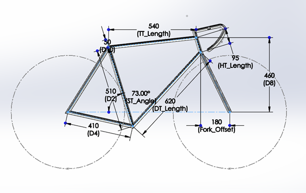
Let’s start with the frame geometry. There are some basic geometrical
properties I would like to determine, such as the optimal seat tube angle.
I can sketch a bike frame using a 3D sketch in SOLIDWORKS to get started.
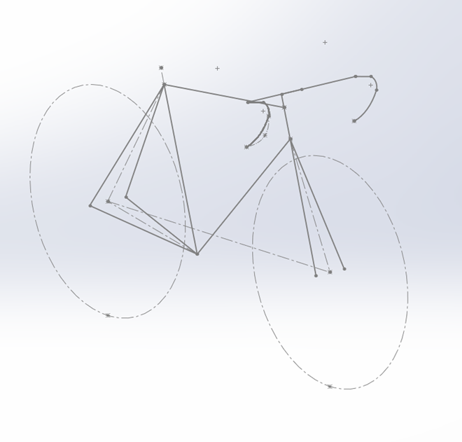
You cannot analyze sketch elements with the
simulation tools, so we need to have some 3D geometry. I can use Weldments to complete the
basic layout and start a static analysis. The Weldments will act as a
simplified analysis tool. As long as the chosen Weldment profile is
axis-symmetric, its properties (such as weight, material, thickness) will not
matter. There are many benefits to using Weldments at this stage including
ease of modeling, and reduction of analysis time (solution times for beams are
significantly lower than solid bodies). I am not interested in exact values.
In fact, the values are arbitrary. What I want is to determine frame geometry
that is optimal for power transfer.
In order to perform a static analysis to study the dynamic behavior of a
bicycle frame, it’s important to make an assumption:
-
Deflection of a frame due to a static steady-state load can be used to
estimate the deformation behavior of the frame under dynamic loads
It’s important to keep in mind that this will give us an idea of the
deflection, as it is an idealized and simplified analysis.
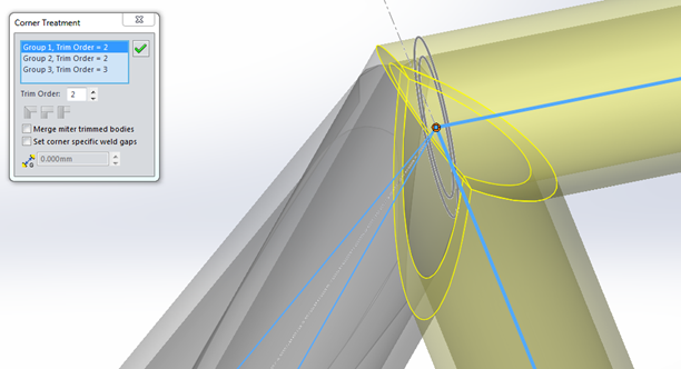
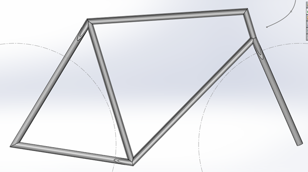
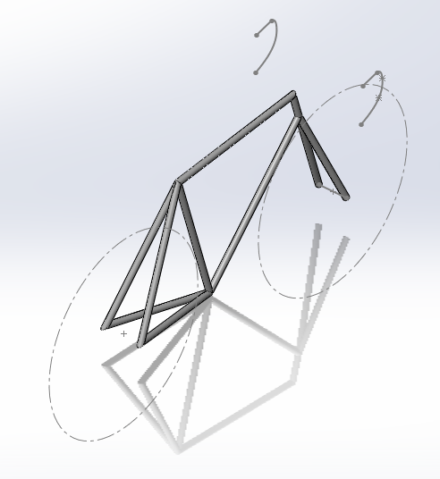
After inserting the Weldments, I applied corner treatments to closely
represent the final frame geometry. With the beam simplification that I will
use later on it doesn’t matter too much, but it does look better.
Cross-Section View
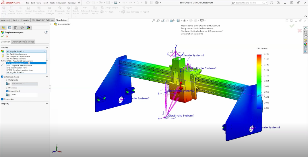
Since it is not possible to incorporate remote loads with beam analysis, I
will have to temporarily model the handlebar to simulate the loads experienced
by the frame. The first scenario is a rider accelerating. There is a pedaling
force and torque at the bottom bracket area. On the handle bars we can expect
an induced moment due to pulling on one side and pushing on the other.
Finally, we can account for a lateral force on the bottom bracket which
represents the pedaling inefficiency as well as the offset of the rider’s body
weight (assuming that the body is angled toward one side).
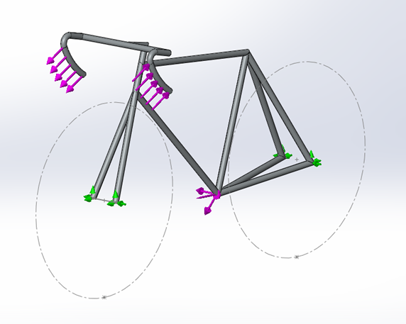
Acceleration Analysis
The areas of the frame that are attached to the wheels will have an
‘Immovable’ type of fixture. This will allow rotational displacements but
eliminates any translational degrees of freedom.
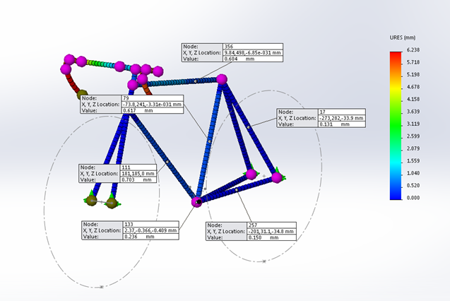
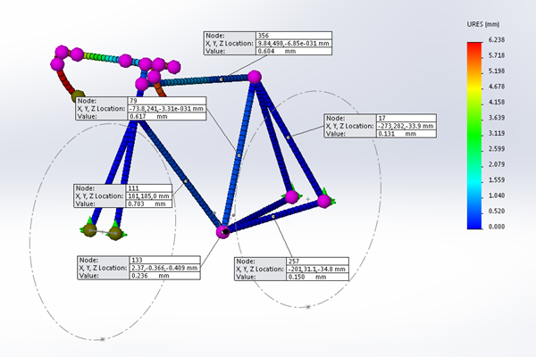
Displacements Due To Acceleration
The second scenario is a rider decelerating. I will assume that the rider has
both hands on the handlebar, feet on the pedals, and not seated on the saddle.
The same ‘Immovable’ fixture will be applied as before.
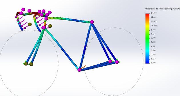
Stress Due To Deceleration
Now that the scenarios are set up, I can choose parameters that I would like
to optimize. I’ll start with the seat tube angle.
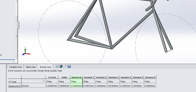
By selecting the seat tube angle as the parameter to change and applying a
‘minimize displacement’ goal for the frame geometry I can see that the optimal
angle is 73 degrees.
A similar approach was taken to determine the optimal head tube length, down
tube length, and fork offset. The results can be seen in the image below.
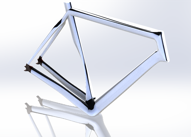
To summarize, the goal of this first part was to determine the geometry of the
frame. Weldments with constant axis-symmetric profiles were used for their
ease of use, and quick analysis properties.
Now that the geometry is set, the next step is to use surfacing techniques to
set the tube shapes.
Stay tuned for more on this series. Thanks for reading!