SOLIDWORKS has a unique and powerful type of assembly component pattern for
setting up patterned components along an open or closed path to dynamically
simulate a roller chains, cable carriers, and power transmission systems. This
new feature was introduced in
SOLIDWORKS 2015.
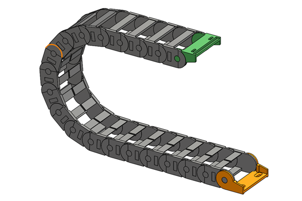
In this 3-part series, we’ll take a look at how to set up a generic energy
chain along with special cases and considerations for performance and optimum
behavior.
Before we start to assemble this thing, let’s first look at how the individual
components are mated together. The fixed bracket (orange) is fixed to the
origin. There is a component that contains only a sketch (purple) to define
the shape, or path, of the chain that is mated to the Front and Top planes,
which means it can move back and forth (parallel to the Right plane). The
floating bracket (green) has only a parallel mate to the top plane. And the
link component (grey) has no mates applied.
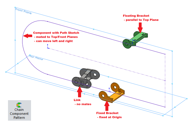
Now when we choose the Chain Component Pattern, there are 3 options: Distance,
Distance Linkage, and Connected Linkage.
Distance
individually or with the selection manager, then define the number of
instances, or choose to fill the entire length of the path.
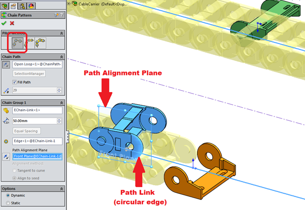
Next, choose the component, its spacing, and its Path Link and Path Alignment
Plane. The Path Link is a location reference that “attaches” the component to
the path. In this case it’s a circular edge, which defines an axis that
pierces the path. The plane in the link is centered and sets the orientation
of the part to the path.
If you fix the component with chain path sketch, you can can drag the link
along the path and see the entire chain move. If the path sketch part is free
to move left and right, you can drag that component and the chain will move
accordingly. In this mode, the patterned components are oriented exactly the
same as the “seed” or original link, so if you are dragging the link and it
rotates (because it is not entirely defined by selections in the feature), the
components in the chain, regardless of the position along the path, will also
rotate in the same way.
Distance Linkage
along the path, but still allows for a defined spacing. In this case, we’ll
just select the opposite circular edge of the link for the second Path Link
which will fully attach it to the path.
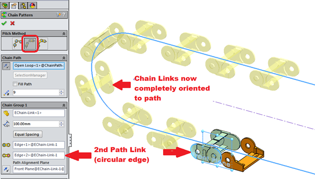
Now, when we drag the path or the link, the chain components follow the path
and stay oriented to it.
Connected Linkage
variable and connects the links. Let’s define this chain to have 19 links.
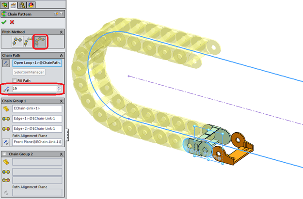
The feature uses the same two Path Link selections to connect the instances of
the link component to each other.
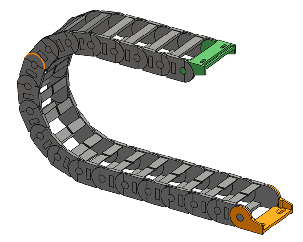
To finish the chain and make it something you can use in a higher level
assembly, you would mate the first link to the fixed mounting bracket, and the
floating mounting bracket to the end of the chain then when we float the path
sketch component, the energy chain behaves realistically. It even stops when
it reaches the limits of the path.
When adding this energy chain sub-assembly to a top level assembly, there are
a couple of things to do:
-
Since the movement of the component that contains the path sketch is what
determines how and when the chain moves, make sure that component is mated
correctly to other parts in the assembly that will drive the movement of the
chain. -
In order to allow this glorious chain motion, you must set the chain
sub-assembly from Rigid to Flexible.
In Part 2 in this series, we’ll take a look at special use cases of the chain
component pattern such as a closed loop bicycle chain with two types of links,
rotary motion, and using in-context sketches to define the path.


