Recently at Hawk Ridge Systems, one of our customers, Keir B. from L-3 Communications Sonoma, contacted the technical support team for some help with a validation example that he set up in order to better predict what would happen with a more complex real-world model. Keir wanted to make sure he was using conditions that would match the hand calculation he performed in order to gauge the discrepancy (as in any scientific field, the more evidence you have, the better). We, of course, were happy to help. Keir wrote:
“In this study the key result I am trying to determine is the force generated between two parts made from two different materials as they expand or contract due to temperature changes. The forces are created because of the geometric mismatch caused by the different rates of thermal expansion.”
The original model, shown below, consists of an Alloy Steel frame which has a thin 6061-T6 Aluminum plate bonded to it at two ends. The whole unit is cooled from a room temperature of 20 °C down to -55 °C, or -67 °F for us Americans (thank goodness for SolidWorks’s built-in unit conversion).

Because Aluminum has a higher thermal expansion coefficient than steel, the plate should shrink more than the frame, creating a tensile force in the plate due to the bond between the two parts. We can predict the expected deformation δ of the plate using the thermal expansion equation:
![]()
…where L is the original length of the plate, ΔT is the temperature change, and a is the thermal expansion coefficient. Because we actually have two materials in this example, the equation can be simplified by analyzing the plate only and using the difference between the two material properties. Again, Keir wrote:
“Steel expands (or contracts) at 1.1 x 10⁻⁵ /°C; Aluminum expands (or contracts) at 2.4 x 10⁻⁵ /°C. Therefore the difference of 1.3 x 10⁻⁵ /°C will cause a force to be generated within the structure proportional to the amount of temperature change.”
Using this assumption and throwing the appropriate values into the equation, we get:

Finally, we can use this deformation to calculate the tensile force on the plate:

…where A is the cross-sectional area of the plate and E is the elastic modulus of 6061-T6 aluminum. We get:

So, how does SolidWorks stack up in comparison? To check, we will first want to make sure our study setup has the exact same assumptions that we are using for our hand calculations. In this example, that means analyzing the aluminum plate only and changing its material properties to use the net thermal expansion coefficient of 1.3 x 10⁻⁵ /°C.

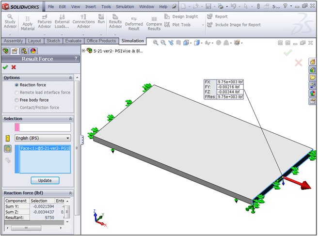
In our study, the part is restrained so that the end faces (where the plate is attached to the steel frame) cannot displace lengthwise. Because the part is in static equilibrium, the tensile reaction force at end of the plate will be equal to the required force value we obtained from the hand calculation.
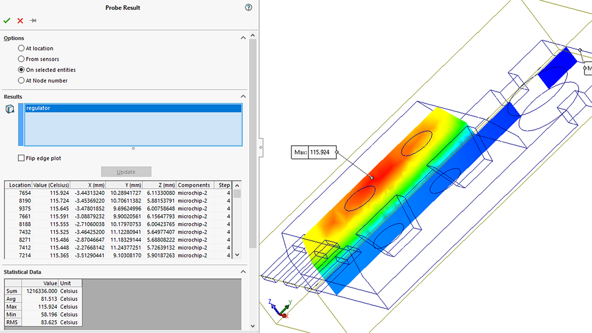
After running the study, we can use the List Result Force tool from the Results folder to obtain the reaction force:

How do you like that?! Thanks to very simple geometry and a good mesh, we get a lengthwise reaction force of 9,750 lb, which matches up exactly with our hand calculation. The reason is simple: SolidWorks Simulation is using the same equations to get its solution as we are – after all, that’s why all the same values need to be entered somewhere in the software, be they the part geometry or material properties!
Of course, the real-world result from a physical test would differ somewhat from this simplified case, because we discounted the steel frame which in reality will also displace. That’s why the original model would not be a good comparison to the simplified hand calculation. So, the moral of the story is: make sure any study you create for comparing to hand calculations has the same conditions and assumptions! Do your homework, and you should get a warm, comfy, reassuring result each time.