
Thanks for joining us in Part 2 of this content series! In Part 1, we covered the initial setup of our Mark Two, which included loading material and walking through the cloud based Eiger software. In this part, we will be covering the design and final outcome of our Markforged tool caddy, which was our first major print!
The initial goal of this project was to design a part that could organize tools that were used with every print. The items which we wanted to organize in the caddy were:
- Bed level shims
- Allen wrench
- Glue stick
- Needle nose pliers
- Scraper
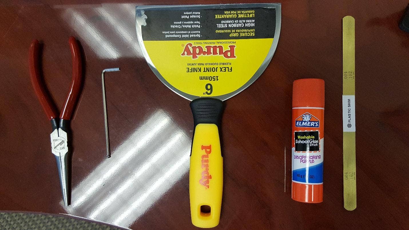
We started the design by importing an accurately scaled sketch picture of these items and working around it. After doing this, the first iteration was made.
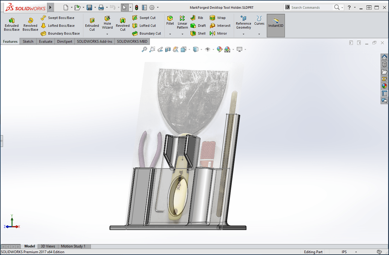 The initial tool holder, designed and shown in SOLIDWORKS 2017.
However, we ran into our first challenge, which was related to the height of the part. Due to the dimensions of the shim slot, the part could not be printed unless it was placed in a less than ideal orientation. We chose to remove the slot entirely, rather than shorten it.
After removing the shim slot, we ran a test print of what we had so far. In its current form, the tool holder printed with almost no complications.
While the part that we printed was certainly usable, we had a few additional goals that we wanted to meet, which included using less material overall and redesigning the shim slot.
When redesigning the shim slot, we had several different ideas, including the addition of a channel near the rear base.
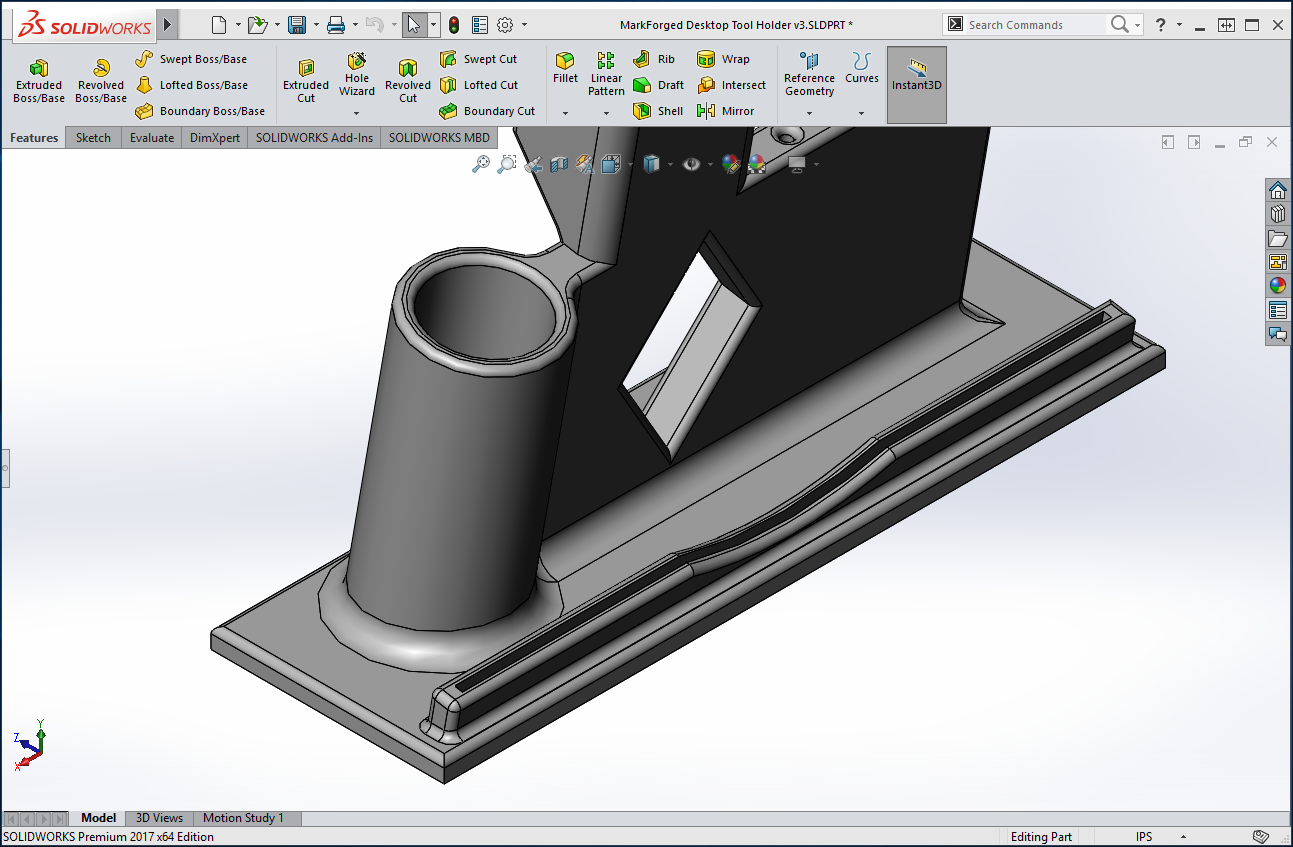
However, most of our ideas involved adding more material, rather than saving it. Towards that end, we eventually decided to add a slot inside the base itself. While working on the slot, we also removed some material from the plier area.

This slot configuration presented its own challenges, however. With an overhang that was parallel to the print bed, this particular area would require printed supports. Since the slot itself was 8 inches deep, support material would be difficult to reach without potentially damaging the part itself. To prevent this, we needed to choose a different design for the slot.
For the slot entrance, we first wanted to make sure that each shim could be accessed, even when they were fully inserted. To accomplish this, we created an arc-shaped cut from the top of the base to the shim slot.
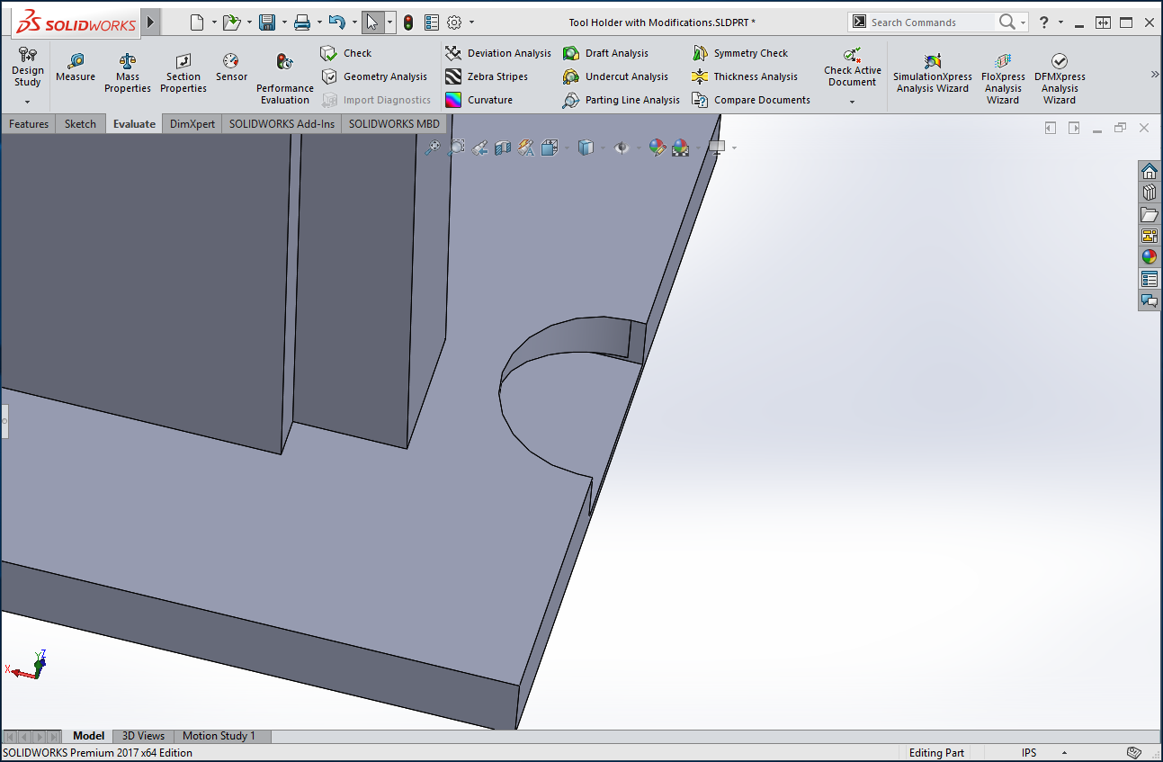
From here, we tested several different bridging features, including chamfers and arcs. Eventually, we found that two steep angle extrudes worked best. These extrudes ensured that no material was bridging over open space. The small size of the slot itself helped to ensure these features printed successfully, despite the fact that they are also at a steep overhang.
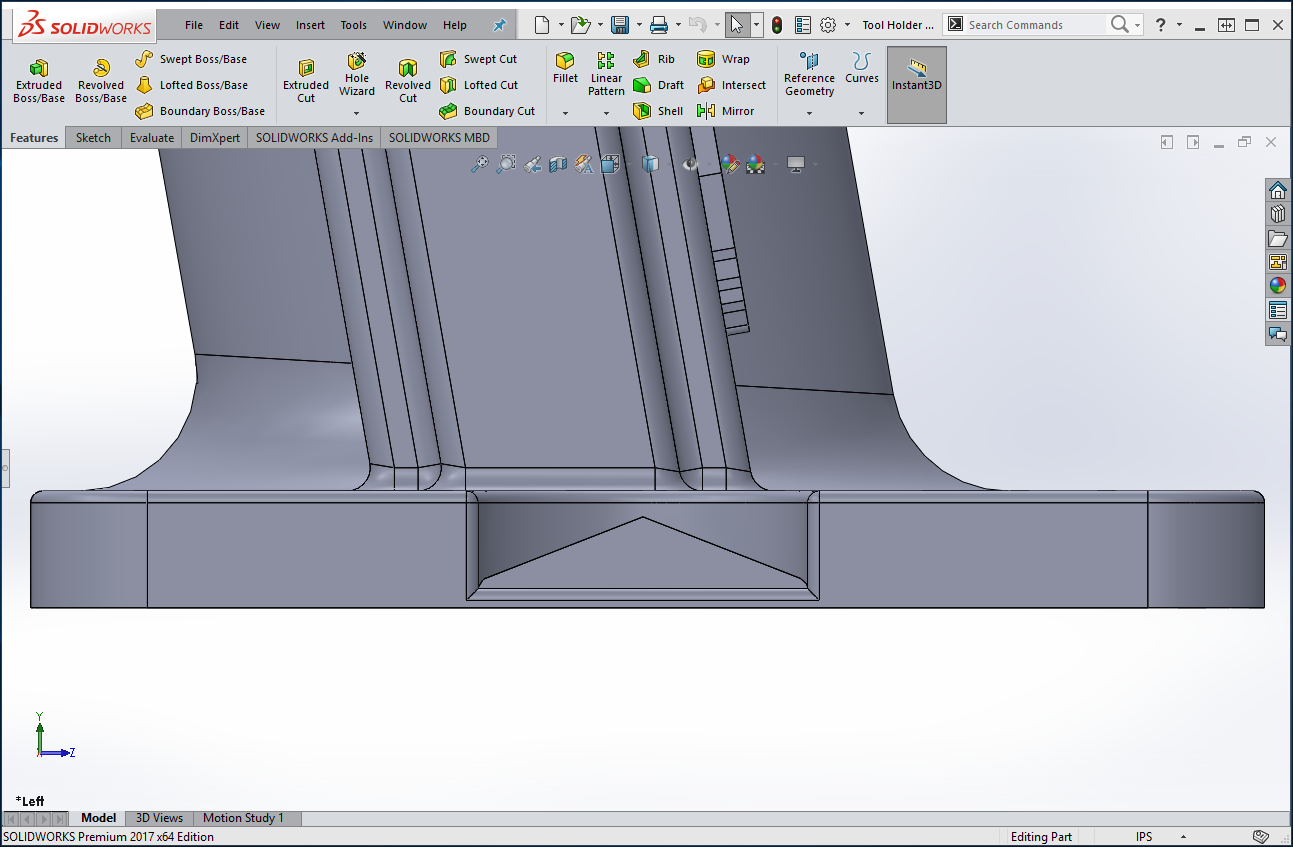
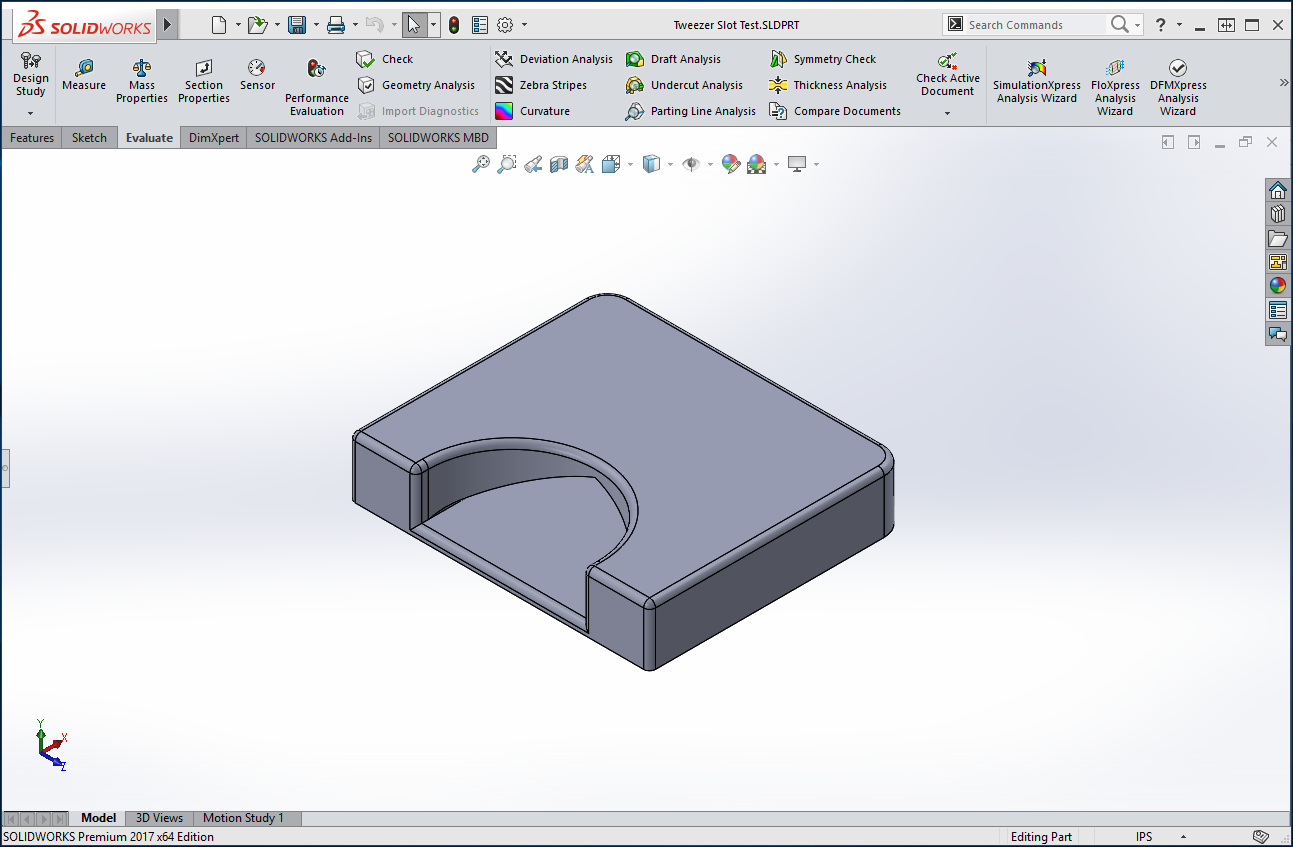
To effectively test our different slot designs, we cut away most of the surrounding part. This allowed us to specifically test print our slot iterations, rather than spending time and material on a full reprint.
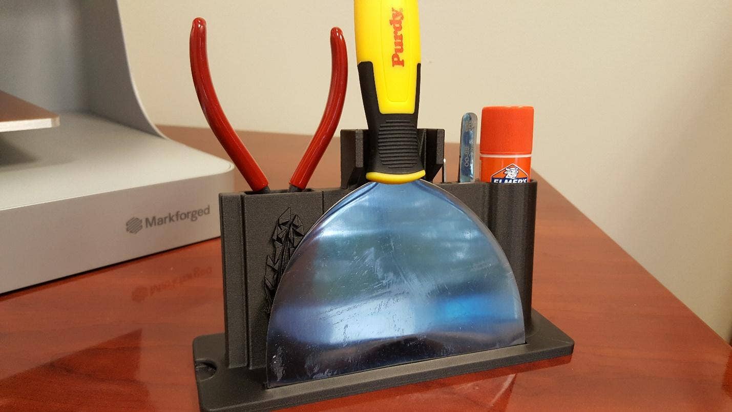
Once the design of our shim slot was finalized, we put the finishing touches on our tool caddy. One of the final major changes was flipping the placement of our scraper. This provided us with a safer way to store the sharp tool, in addition to saving material by reducing the overall height of the caddy. To accommodate the flipped scrapper, we added a small cut in the base, ensuring that it would not move. We also converted the original cut in the center of the part to a diamond shape, which would print better when compared to the original oval shape.
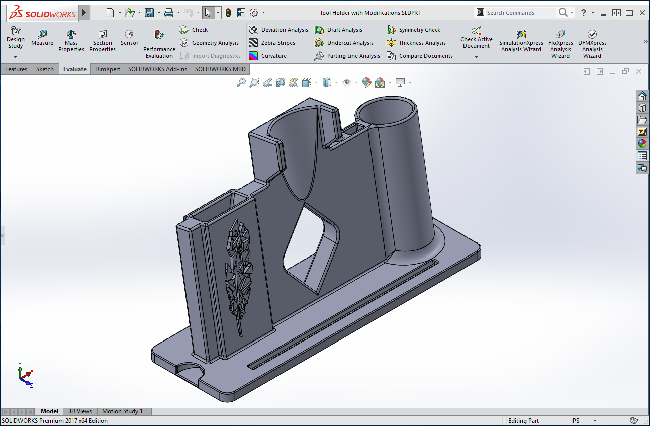
Lastly, we cut a slot for the included tweezers and added a bit of flair, in the form of our Digital Manufacturing logo. Of course, this did increase material usage, but even with the addition, we were still using about 18% less material when compared to our original test print, which did not include a shim slot. Not too shabby!
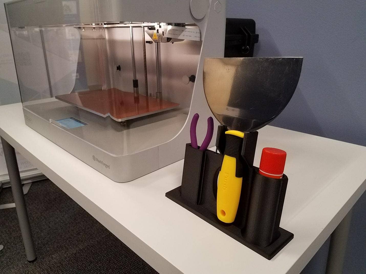
When the changes were complete, we re-printed the tool holder. Here are the results!
During this project, we were able to design and print a custom component, which would have taken much longer to complete via traditional methods. As mentioned previously, we did not take advantage of the fiber inlay process that is unique to Markforged, which greatly increases the strength of printed parts. For more information on the benefits of printing with Markforged, please feel free to see our previous blog post here: https://www.hawkridgesys.com/blog/3d-printing-markforged-day-strong-parts/
You can also learn more about Markforged from their website, found here: https://markforged.com/
For more information, check out our YouTube channel, get a 3D printing quote or contact Hawk Ridge Systems today! Thanks for reading!


Nowadays everyone got a fantastic 3D printer and why not it is best in what it does, But it turns into shame when it shows error and you do not have a clue how to fix it.
These extrudes ensured that no material was bridging over open space. The small size of the slot itself helped to ensure these features printed successfully, despite the fact that they are also at a steep overhang.
So why not include the link to this file, for the people that own a markforged to use?