To begin the design for my finger plates I first had to take some measurements of my finger. I measured my finger to have a diameter of around 20mm at the thinnest section, 25mm at the thickest section, and a length of about 110mm. Using these dimensions, I revolved a cone to represent my finger. Figure 1 below shows the solid body used to represent my finger.
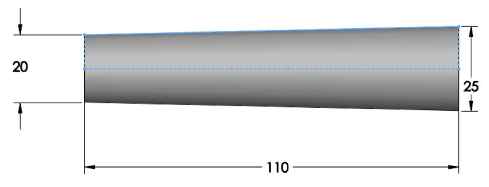
Figure 1: Solid Body Representing Finger
The next step was to break the “finger” into sections which would represent the plates. In order to do this, I created a series of parallel planes. The options in the property manager let me define 7 planes and I only had to adjust the spacing until it looked right. The Split Line tool then segmented the face and gave me edges that I could relate my sketches to when creating the finger plates. Figure 2 shows the final results of the sectioned finger.
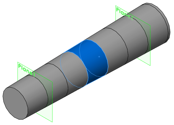
Figure 2: The “Finger” Split into Sections for Aligning the Plates
Each finger plate was created using the Revolve feature. A line was created and then some specific relations gave the line its shape. I put a 1 mm clearance between the line and the link it overlaps with. I also put a vertical relation and 1 mm dimension in the edge that was created with the split line. This diagonal line creates a plate that is tapered inward. This was necessary because without it the biggest plate would be so large that there would be no room to move the fingers. I leaned that the hard way with the first revision of my design. The sketch was revolved about the centerline of the finger and was a thin feature with the material applied to the outside of the sketch. Figure 3 is the sketch used to create the smallest finger plate. This step was repeated to create 6 unique plates.
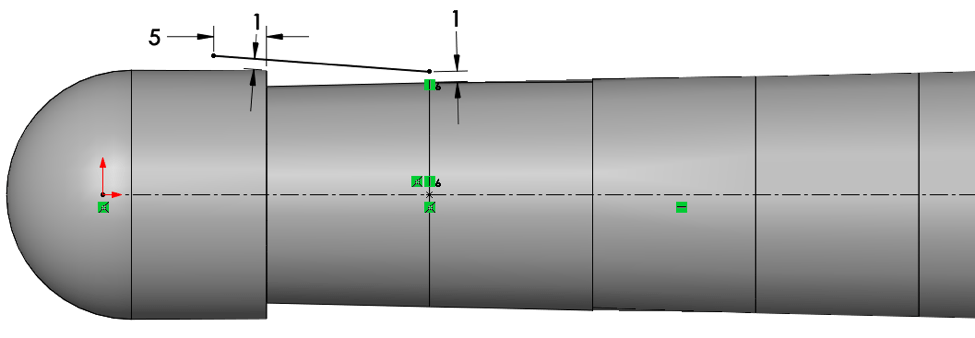
Figure 3: Finger Plate Sketch Showing Dimensions and Relations
Multibody techniques were used in the creation of this part. I choose to use this method to generate my part because I wanted to be able to easily size the parts to one another for clearance dimensions. A multibody part also has no relative motion so I won’t accidently move a component and lose clearance or change related geometry.
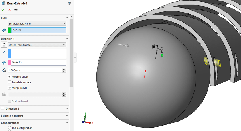
The next step was to connect all the components together. Traditionally this was done with rivets but since I was using a 3D printer to manufacture this part I built pins directly into the pieces. The pins were created with a simple Boss Extrude but I used some unique options like Extrude From Surface for the start condition and Offset From Surface for the end condition. This saved me from having to create extra sketch planes before the extrusion and trimming operations after. Figure 4 is an image of the property manager and graphics preview for creating the pin. The start condition is from the surface of the fingertip revolve and end condition is offset from the outside surface of the plate it is attaching to.

Figure 4: PropertyManager of the pin feature displaying start and end conditions
When generating the slot I used the Offset Entities sketch command to create a circle that has a .4 mm clearance for the pin. The offset circle was construction geometry with the arc of the slot related to it; this was convenient for when the pin was modified because the slot would automatically resize itself and maintain the appropriate clearance.
To test the clearance and mobility of the fingers I had to generate an assembly. This was done by using the Save Bodies command. This command saved each of the solid bodies in the original part file as individual part files and created an assembly with all the parts in it. The newly created assembly had all the components lined up the way they were in the original part file but were fixed in space. This meant that I had to add mates and unfix any of the components that I wanted to be able to move, but while I had the assembly in this position I decided to create a configuration to represent the printed position. I then used the Clearance Verification tool to verify that there is enough clearance to print the parts. I set the tolerance to 0.4 mm so anywhere with parts closer than that would be flagged. Of course, the clearance verification passed because the parts were created with the 0.4 mm offset but it never hurts to be cautious and double check.
The next step was to ensure the parts would not separate from each other and that the pins were long enough. To test that aspect of the design I created a new configuration and used the Move Components tool. Inside the property manager I selected Stop on Collision. This allowed me to drag a part freely until it collided with another. Using this technique, I determined the length of the pins which let the finger components bend and rotate but also kept the parts together. Figure 5 is a brief example of the move components tool. To validate the design for myself I also rotated the component as well as translate it.
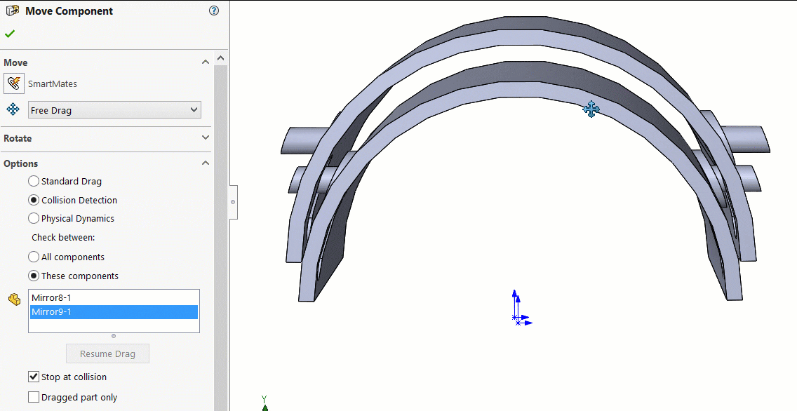
Figure 5: Video of move component tool to test the connectivity of the components
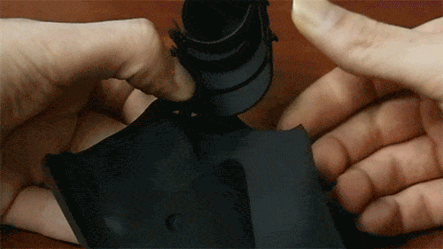
In my first print the finger components separated from each other. I was really disappointed because all of my testing in the virtual world said the contrary. What I neglected to consider was the flexibility of the material. Since it was so thin it would elastically deform and allow the parts to separate. I was impressed with the strength of the material and its flexibility. The video below shows that I can completely flatten the part and it will return to its original shape.
To ensure the finger pieces did not separate for the final design I put a head on the end of the pin. I was going to do this initially but decided not to because I wanted a sleeker, flush look on the pins and felt the heads looked bulky.
I also did a Motion Study to ensure that the part would have the same range of motion that my finger does. For the motion study I used the assembly file and fixed the component closest to the center of my hand. I removed all the mates so the simulation did not unrealistically constrain the degrees of freedom and added contact sets between all the components that would make contact. I added gravity so the components would flop naturally. The videos below are a side by side comparison of the simulation and reality. The differences are of course the dampening on the motion caused by friction and the restriction on the range of motion as the fingertip impacts the back of the hand. However, both hold together and move in the same way so I will deem my motion simulation a success.
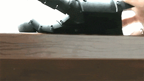
Figure 7: Video Comparison of simulation and reality.
Thanks for reading part two of this blog series and if you are interested please read the rest. Click here to read Creating Fully Functional Medieval Armour – Part 1. For more information, request a SOLIDWORKS 3D CAD quote or contact us at Hawk Ridge Systems today.