SolidWorks navigation in the graphics area can sometimes be a challenge. There
are some very useful clicks to help you see your model exactly the way you
want! Check out the list below:
1. [Space Bar]: Hitting the space bar brings up the
Orientation dialog, so you can select on the view you wish to see.

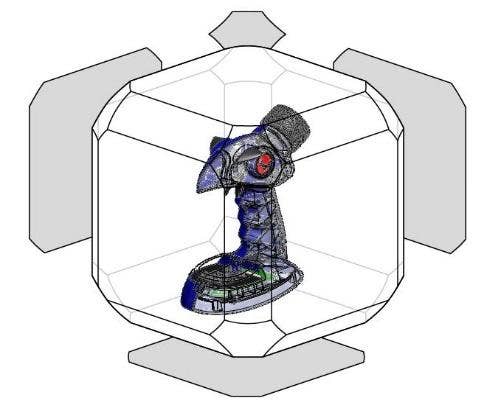
2. [Ctrl+Space Bar]: This allows you to see the View
Selector cube! Then you can select the cube face for the orientation in which
you wish to see your model.

3. Reference Triad: You can click on the reference triad,
in the lower left-hand corner of the graphics area, to see your Front/Back,
Left/Right, and Top/Bottom views.

a. Clicking once on the red ‘X’ gets you the Right view, clicking
again will spin the model 180 degrees to get you the Left view.
b. Clicking once on the green ‘Y’ gets you the Top view, clicking
again gets you the Bottom view.
c. Clicking once on the blue ‘Z’ gets you the Front view,
clicking again gets you the Back view.
d. Alt+Clicking on X, Y, or Z rotates the model around that axis
at set angle increments (Tools->Options->View->View
Rotation->Arrow Keys).
e. Shift+Clicking on X, Y, or Z rotates the model around that axis
at 90 degree increments.
4. Select a face, then use the Normal To: This allows you to look normal to any face you had selected., i.e. the face
will be parallel to your display screen.
![]()
Note: You can specify the exact orientation by pre-selecting two faces
before hitting the Normal To button. The first face that is clicked
will orientate to be normal to your screen; the second face will be facing in
the up, or top direction.
5. [Ctrl+MMB] (Middle Mouse Button): this allows you to
pan your part/assembly across your screen. To get this motion hold Ctrl+MMB
and move mouse in the direction you wish to pan the part. In a drawing you
only need your MMB to pan the drawing across the screen.
6. [Alt+MMB]: Rotates, or “rolls” the part in 2D around a
vector normal to your screen. Move your mouse around in a circular motion to
get this behavior.
7. Rotate about a Vertex, edge, or face: Middle Mouse
Button (MMB)-click a vertex, edge, or face (to define the entity to which you
want to constrain it); then hold down the wheel and drag as you usually do to
get the motion desired motion. This is great for spinning a wheel, swinging
a door, etc.
8. Shift+MMB: Zooms the part In and Out. You need to hold
Shift+MMB and by moving the mouse up, you zoom in, and by moving it down, you
zoom out.
![]()
9. [G] key: Brings up magnifying glass so you can zoom in
to a smaller, local area within the glass circle.
As you can see, there are numerous ways to navigate the world of
SolidWorks! I hope you’re more successful in saving time and maneuvering your part
around with these tips on model orientation commands.


What are the Angle Orientations, relative to the three standard planes? What is the 3D protractor for the space. For example, if the front plane is normal to the screen, and you an object’s right side clockwise are you moving form 0 degrees out from the screen. Are the numbers positive or negative, or is say 359, 57, 56, or 1, 2, 3 degrees etc.
The reason I ask, is to figure out the angle orientation of helices starting at different angles when sketches are on different planes. Another words, If you start on the front plane, what angle is the helix starting at?
Hope this makes sense.
Hi Greg,
Please see this image for reference: http://imgur.com/a/uiUY9
For further clarification please contact your reseller. It should following standard orientation of graphing.